Saturday, 29 September 2018

Stone Walling - Realistic Brick Compound

This method of stone walling uses Bromley Crafts Realistic Brick compound https://www.craft-products.com/realistic-brick-compound.php. The process starts with the wall structure w made from mountboard and glued to the base. Originally the walls where painted a light grey but after seeing timms work on the forum using a much darker background I opted for painting the walls black. Work started with the gate posts.


The edges of each gateway where masked off and a layer of brick compound applied, masking tape removed, allowed to set and a layer of matt varnish applied to lock it in place. Before adding the varnish any stray blobs or irregularities can be removed with sandpaper or a scalpel.
Next the main stone work was applied. The rough stone stencil provided by Bromley just doesn't reflect the stone shape common to my local area so I set about making my own stencil. I drew out a stone pattern on paper then using a sheet of, I think 190 micron thick, Mylar layed over the paper pattern I cut out the shapes in the mylar with a craft knife.

The top of the wall was masked off for the capping stones and the compound applied in a rough uneven layer. (There are various youtube videos depicting how to use the realistic brick compound)

Finally the capping stones where done by using millimetre wide masking tape layed approximately 1 mil apart and a layer of brick compound applied
This method is great for fast production of stone walling on the side of sheds etc, but I felt wasn't the effect I was looking for with boundary walls so the above was scrapped and a new method used Stone Walling
Below are some photos of a shed produced using the compound


Stone walling - Kapa Line Foamboard

My preferred method for modelling stone walling is this one, the methodology comes from David Neat, whose excellent website can be found here 
Here's the method I used. I cut the board to the height I wanted the walls to be without the capping stones. Then peeled the paper backing off.

To get stone pattern right I took a ride out onto the moors taking snaps of various bits of stone wall.


I then drew out a suitable pattern in pencil on the board.

Using a pointed craft tool I then carved out the stone work. I found for smaller bits the line had to be cut with a blade before passing over with the point or the material would just rip. The board is much easier to carve than clay meaning longer periods of time could be spent on carving making this process a faster one. The properties of this board mean that by pressing in individual stones the uneven nature of drystone walling could be replicated.


In the next photos ignore the paint, this was me experimenting with the best paint method. I will explain painting later.
The two wall pieces where glued back to back with a five millimetre strip of mountboard stuck at the bottom to make the bottom wider than the top like a realtrue wall. Gate posts where made using 5mm Foamex. Cut to size and glued back to back it was roughed up using 80 grit sand paper to back to give a cut stone look. These where glued to the end of each wall section.

Capping stones where next. These where made of mount board. Lengths where cut the width of the wall and individual stones cut at various lengths from these strips. All cutting was done using a pair of tin snips as this gave a nice rough cut that better resembled stone than a perfect straight cut from a knife.

First layer was layed horizontally.

And then the rest where stacked together glued in place with UHU adhesive.

The other part to mention is corners. I had a look at how corners where in real life. And from here replicated in miniature. A mitre joint on the end of the board meant seamless transition from each side. The rock holding the capping stones was made in the same way as the gate posts.

The last step was paint. A base layer of Acrylic 'Naples Yellow' was applied. This quite nicley matches the colour of local fresh cut sand stone. Once well dryed a watered down wash of black poster paint was applied, this highlights all the nooks and cranies and defines the individual stones, as well as dulling down the yellow. A layer of matt varnish was applied to fix it in place. Next various brown and green shades of acrylic where dry brushed onto the wall until it was dulled down to colour similar to my reference pics. More greens where added to one side of most walls to highlight where moss would be growing more as the sun reached areas of wall but not others. A final layer of varnish fixed everything in place and helps protect the board from warping with damp. That brings how the walls where done to a close.


Yorkshire Slate Roofing

This guide demonstrates my method for modelling slate.
The barn I'm building is roofed in Yorkshire Falgstone Slates which I needed to replicate in miniature. This was done using mountboard. First it was cut into rectangles of decreasing sizes as the slates get smaller the further up the roof they get. Then the edges where trimmed to round them off.


Slates aren't a continuous thickness so some more work was needed to get the right look. Using a craft knife I peeled the edges, weathing them and adding in the appearance of layers like real slates.


With the slates now ready they can be layed just like the real thing. For the barn I want the roof to be removable so a border is fitted around the roof lines (painted black) with a lip underneath that the main roof sheet (white in the photo), again made of mountboard sits ontop of. Slates are then glued to the main sheet, overlapping the border.

This is built up along the whole roof. When reaching the top it was necessary to put a shim of cereal card inplace to glue the top layer of slates too, as otherwise they would be glued to the border and the roof wouldn't be removable.


Paint is next. A liberal coat of Reeves Naples Yellow Acrylic was added, and to get the gritty texture of sandstone tile grout was sprinkled on and blended in while wet


The paint now needs weathering, to do this I apply two washes of black acrylic, watered down by about 50% and really scrubbed on with a paintbrush so that only a thin layer is applied. Making sure that all the cracks and crevices are highlighted by the black.
Thi


Wednesday, 15 August 2018

1/32 Telescopic Rams How To Guide

Be it a front loader, tipping trailer or other piece of machinery telescopic rams are everywhere on a farm so being able to model them is a great skill.
There are a number of off the shelf options available from the likes of farmmodels.nl but the best and cheapest way to get a ram the perfect size is using car aerials. These are available on ebay for as little as 99p. The issue comes with the fact that generally they are too long, or have too many sections to be used straight on a model. Therefore they need cutting down. this guide demonstrates how to do that.

Starting with the aerial out of the packet the top nib and the bottom hinge need removing


To remove the hinge I use a set of modelling pipe cutters, a craft knife will do the same job but will blunt very quickly.

Hinge removed

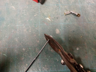
The nip is simply cut off with a set of tinsnips

Pushing down on the top of the aerial the whole unit will slide out of the outer tube, along with two copper shims.

Keep these shims safe as they will be needed later.

Repeat the process till you have removed each section of rod from the aerial. At this stage you can get rid of any sections you don't need. In this case I am making a five stage ram so only the very smallest rod wasn't needed. In the case of a silage trailer you may want two rods from the middle depending on the desired diameter.

I find using a craft knife for the next bit is more accurate than the pipe cutters and also doesn't crush the tube as much making replacing the copper shims easier. The length of the ram is decided and each part cut to size, the first and last sections are cut longer than the others to allow room for eyelets to pivot from. The knife is used to roll the tube along deeply scoring the metal, the tube is then snapped off at the correct length. Measure the length from the curled end of the tube and NOT the end with a hole drilled in.

Some deformation of the tube will occur, a diamond file is used to re-round the tube so it will slide over each section better.

Using a punch a hole is marked out ready for drilling the hole the copper shim sits in.

The hole is drilled out, matching the diameter of the original hole. Here I have made a simple jig to hold the tube while drilling compromised of one large piece of mount board, with a smaller piece glued on top that the tube pushes against. The tube may need tidying with the file again at this stage to make sure it is round and unobstructed.

This process is repeated for every section of tube.

The copper shims can be put back as they came out but this will severely limit the length of travel achieved by the ram. Therefore I cut the shims down so they are the same length either side of the indent. This is done with tinsnips, then a pair of pliers are used to re-round the shims.

The shims are placed back with the indent sitting in the hole. And now the tricky bit.

Starting with the smallest two tubes the smaller tube must be pushed back into the larger one, and the copper shims pushed in with them, this is why it was important to file the tubes back to round. If you are having trouble getting the shims in try flaring the edges of the tube out with the file or a punch.
Repeat for each section of ram, going up in size each time.

To make the top eye I have squished the tube with pliers.

The drilled a hole in the flattened tube.

I drilled the bottom eye along with all the shim holes so that leaves the finished ram ready to fit in the trailer.